
Benchwork
Over the past 50 years, on the building of a model railroads either for myself or for other people, I have learnt many aspects of model making. One aspect is, you never stop learning. I still am.
When
I first started into the realms of Railroad Modelling, the knowledge I gained
from watching other people work gave me much pleasure.
The questions I asked, of these people I watched, must have run into the
thousands. All were very helpful in putting up with this very young teenager who
wanted a railroad for himself.
What I have learnt over these last 50 years has given me much more pleasure than you could imagine. Now, I would like to share that knowledge with you.
This
is going to be an in depth study into how to improve your skill level by either
laying track for bullet proof running or making scratchbuilt structures
plus - Tree making - Track ballasting
- Lighting (for that theatrical approach) and to photographing the layout, when all
is ready. Whatever the subject, I’ll try and deal with it in as much detail as
possible. Okay, lets make a start.
The
Woodwork for open grid baseboards
All
wood used in the making of a baseboard has got to last for years, so get the
best wood possible. Seasoned wood is the best, as it will not warp. The size of
the wood is also important, I, like most other enthusiasts, use 3” or 4” by
1” for all main frames. 2” by 2” I use for the legs. The meaning of open
grid baseboards means just that. If your baseboard size is an 8’ by 4’ your
open framing will be every foot. This allows you to build below as well as above
the baseboards for scenic details. More on this aspect a little later. See fig 1
for a drawing of the open grid baseboards.
Fig
1
Represents
one 8’ by 4’ layout.
The
size of your layout might not be an 8’ by 4’; it might be smaller or larger.
Whatever size you make it, just make sure that the open grid baseboards are
spaced at one-foot intervals.
The black squares in the corners and around the edges represent the 2” by 2” square legs.
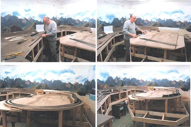
There are various ways to make your Benchwork from Lgirder to cookie cutting. I use a similar method to Lgirder inasmuch as I use stilts on an open grid to raise the main baseboard above the framework to allow scenery to be built below tracks. Also I very often use cookie cutting. For my cookie cutting, I nearly always use ½” Chipboard with ½” insulation screwed to it. For my logging layout, there were occasions were I needed to raise the tracks quite sharply, in this case I would just use 1/8" plywood with the ½” insulation board glued to the plywood. I tend to use a combination of stilts to raise the main board and cookie cutting to raise track work. Photos show both stilts and cookie cutting methods.
There are a number of ways to place "Stilts" to the main frame for raising the track bed up. 1 is to just use some 2" X 1" and clamp it in place - screw it in, as per photo below.


The other way and probably the best is to use a cutout stilt. These are cut from 2" X 2" timber with a slot to sit on the main base boards, once screwed together, they will never move.
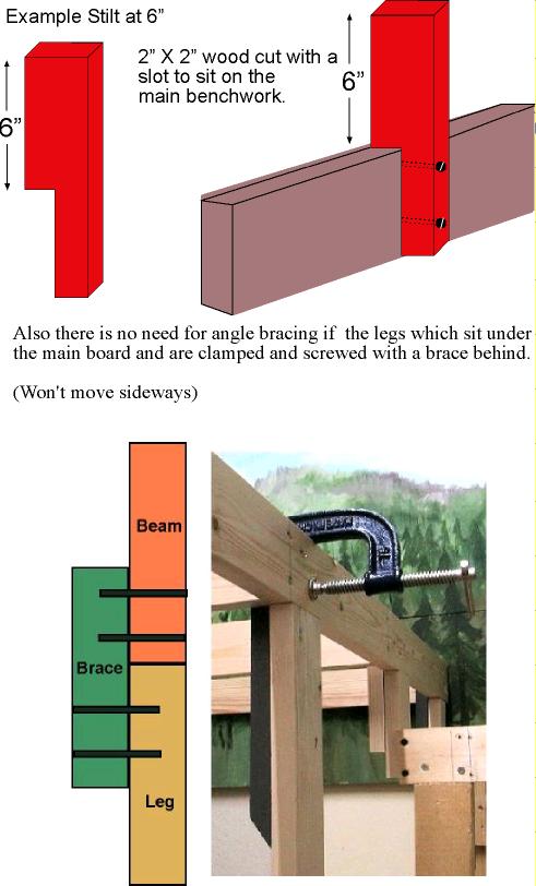
This is my main frame "below", showing just the legs and open grid, at 12" X 18", this is now ready to add the stilts to raise the first level of track work. Also enables scenery to be built below. I shy away from angled bracing as I may from time to time have the need to crawl underneath it. That why I use the brace behind leg and main beam. (Photo above)

Three photos show various stages of cookie cutting, "A" shows the 1/8" plywood and 1/2" Insulation side by side ready for gluing. "B" shows it in place and ready to be lifted on stilts. "C" shows it in place and ready for the track.

Once
the baseboards have been made, you must now make a decision on what material you
are going to use for the track bed. I personally use ½” chipboard with ½”
insulation board (Sound Board) on the top. One reason is for strength (The chipboard) and the
other (Insulation) for easy pinning of track pins when laying the track.
Once the chipboard and insulation is in place, now is a good time to paint the insulation board an earth colour. Just use an ordinary household emulsion paint (Matte finish)
Apart from anything else,
the insulation board will be sealed and easier to cut and it looks nice also.
Now on to laying the tracks, assuming you have a track plan in mind.
Track Laying
These
are the tools needed to lay track.
Needle
nose pliers
Small
file
Rail
cutters
Fine
saw
600/800-grade
wet/dry paper
Track
gauge (Peco
- RED)
2’
Metal ruler
Band-Aid
(maybe)
Knife
(Craft type)
Soldering
gun and solder
Now all that remains is the type of track to use. Probably the best track and points to use in model railroading ( just my opinion) has got to be PECO, unless you require to make your own track.
With PECO track and points, you have the added option of using either code 100 or Finescale code 75. for HO, and for N-scale they do the equivalent. It really doesn’t matter which of the two you use, because by the time the track is ballasted, the entire track will look just fine anyway. Also by using PECO track and points, you will have the added advantage of being able to use the PECO PL10 point motor to fit underneath should you so wish to do so. There is also another PECO addition which can be added to the PL10's, and that is the PL13. This is actually a switch to enable lights to be turned on or off with the throwing of the point (Turnout). The PL10 fits under the PECO point (turnout) and then the PL13 fits under that. So once the point (Turnout) is thrown and the PL13 is in fact wired to say a signal light, it will change from Green to Red if that's what the colours are on your signal.
PECO
also make set-track curves in various radii, which you could use instead of
flexitrack. Flexitrack to my mind is the best way to go
as you can alter the shape in any way you desire.
.
If you want to raise the track slightly to give the impression of a
well-maintained main line, then I would use 1/16th cork sheeting.
Whether you use the cork sheet or not, both ways of laying the track will look
fine when it is ballasted. Okay, let me describe how I would lay one yard of
track. First of all, with a sharp knife, cut off two of the end sleepers to
allow the metal rail joiners to slip on easy. Do this at both ends. Now, after
marking where you want your first piece of track to be laid, place a track pin
at either side of the track on a sleeper (Tie), two sleepers in (Not in the
middle as this will reduce the gauge slightly) Now with the needle nose pliers,
press the track pins into the insulation board. At this stage please check that
the pins have not bent down the edges of the sleepers. If they have, gently
raise them up a little with the knife. At this stage, I assume that the track is
a straight piece and not curved anywhere. If it is a straight piece, then lay
the 2’ steel rule up to the sleepers so as to keep the track straight and the
same distance from the edge of the baseboard. Move along to the end of the track
and repeat the stage of track pinning. When both ends are done, make sure all is
still straight with the steel rule and pin the rest of the track, every five
inches or so, again checking that the pins haven’t gone too far down.
That’s
the first piece down, now on to the next yard of track or maybe a point in you
case. I don’t know, but which ever it is, the same method applies for laying
trouble free running.
Lets
for the purpose of instruction, lay another yard of track onto the first, and
solder the two together. As with the first yard, snip off two sleepers from
either end once again. Place metal rail joiners on to the new piece of track and
place it at the end of the first piece of track. Now very carefully, making sure
that the track is flat on the insulation board, bring it into the first piece of
track. Don’t lift it as you bring it into the other rails as you will bend the
metal joiners and cause derailments at a later date. Just be careful, and take
your time. At this stage, sight down the two pieces of track and make sure that
the two are in fact straight, if they are, then pin the second yard down as you
did the first one. After which you can solder the joints for good electrical
contact.
If
you have never soldered rail joints before, then here is how it’s done. My
soldering gun is of the instant type, press the trigger and it’s on. Some
others need time to heat up. Which ever type you use, make sure it’s hot and
ready for use. Here goes. - With the gun hot, place the tip of the gun or iron
onto the rail joiners and apply the solder to the rails, not the gun or iron, if
the gun is hot enough, the solder will flow underneath the metal joiners for a
good connection.
Some
others need time to heat up. Which ever type you use, make sure it’s hot and
ready for use. Here goes. - With the gun hot, place the tip of the gun or iron
onto the rail joiners and apply the solder to the rails, not the gun or iron, if
the gun is hot enough, the solder will flow underneath the metal joiners for a
good connection.
Remember
the 600/800-grade wet/dry you bought, use a small piece and gently go over the top
of the rails to clean them off. Now run your fingers along the tops of the
rails. If there are any height differences, now is the time to file it down a
little then go over it once again with the 600/800 wet/dry. When you file the track,
just file one way, not backwards and forwards. Don’t forget to run your
fingers inside the track as well. This is what is called Bullet Proofing the
track. As a further check that the two pieces of track a 100% right, grab one of
your freight cars and roll it over the track joints to see if all is well. It
should glide over the track like silk.
The
same method applies for laying points, except not all points are in fact
soldered because some will need plastic rail joiners so as not to get feed back
from the controllers.
When
buying PECO
points, they all come with ample documentation as to how to wire them
up, so there is no need for me to explain how this is done.